RF Measurements
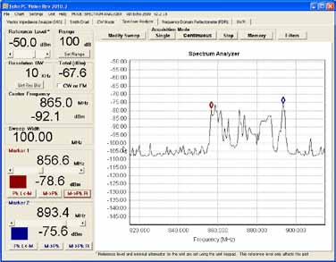
Spectrum Analyzer
– “A spectrum analyzer measures the magnitude of an input signal versus frequency within the full frequency range of the instrument. The primary use is to measure the power of the spectrum of known and unknown signals.”
Vector Signal Analyzer
– “A vector signal analyzer measures the magnitude and phase of an input signal at a single frequency within the IF bandwidth of the instrument. The primary use is to make in-channel measurements, such as error vector magnitude, code domain power, and spectral flatness, on known signals.”
Signal Analyzer
– “A signal analyzer provides the functions of a spectrum analyzer and a vector signal analyzer.”
Frequency, power, modulation, distortion & noise:
– Spectrum monitoring
– Spurious emissions
– Scalar network analysis
– Noise figure & phase noise
– Harmonic & intermodulation distortion
– Analog, digital, burst & pulsed RF Modulation
– Wide bandwidth vector analysis
– Electromagnetic interference
AEA VIA ECHO
Click here to learn about Smith Chart: Smith Chart 101
AN102 Understanding Vector Network Analysis
Vector Impedance Measurements – Most antenna systems are 50 Ohms. This includes the output impedance of the transceiver, the impedance of the feeder cable, and the impedance of the antenna. An antenna is resonant at the frequency(s) where the Impedance (Phase) Angle is equal to zero (0). Refer to the system or radio specifications for operating requirements. The antenna impedance should be at or near the manufacturer’s specification (usually 50 Ohms) across the frequency band of interest.
For good power transfer, cable impedance should match the antenna impedance and transmitter impedance. In addition, the antenna should be close to resonant at the frequency of interest. When the reactance of an antenna is not zero, the current either leads (capacitive) or lags (inductive) the voltage waveform, which results in a lower power factor and lower transmitted power. Thus, having the reactance (series) near zero (near resonant) is desirable
for good transmitter efficiency.
Using a network analyzer to measure vector impedance during antenna alignment improves transmitted efficiency compared to a simple SWR alignment. Below are a list of the measurement parameters available from the VIA Echo. The Echo’s display can provide a graphical display for any one or two of these parameters at a time. If you are new to using a vector impedance analyzer, AEA Technology recommends starting with the Reactance (Total Z) in the left plot and Impedance (phase) Angle in the right plot. A perfectly tuned antenna will show the reactance peaking at or near 50 Ohms at center frequency and the impedance angle crossing zero at center frequency.

